
|
How to Capture the Simulation Screen Display
|

|
|
Screen capture is always required for users to edit manual guide. There are two ways of capturing the simulation screen display:
A. Capture screen on PC;
B. Use “Screen hard copy” function of EasyBuilder Pro:
A. Capture screen on PC
During on-line simulation or off-line simulation, press “Alt+Print Screen” on keyboard to capture the simulation screen. Paste it into an image editing tool and save it.
B. Use “Screen hard copy” function of EasyBuilder Pro
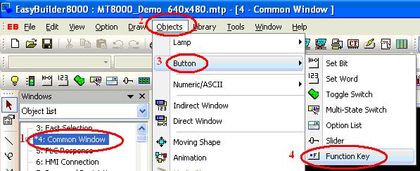
1. Open EasyBuilder Pro project file. Create a function key and check the “Screen hard copy” radio box in the general setting window. Set the printer to “USB disk 1”.
Notice: It is suggested to create the function key object in the “Common Window”, since that the objects in this window can be applied to all other windows;
Click “Object / Button / Function Key”:
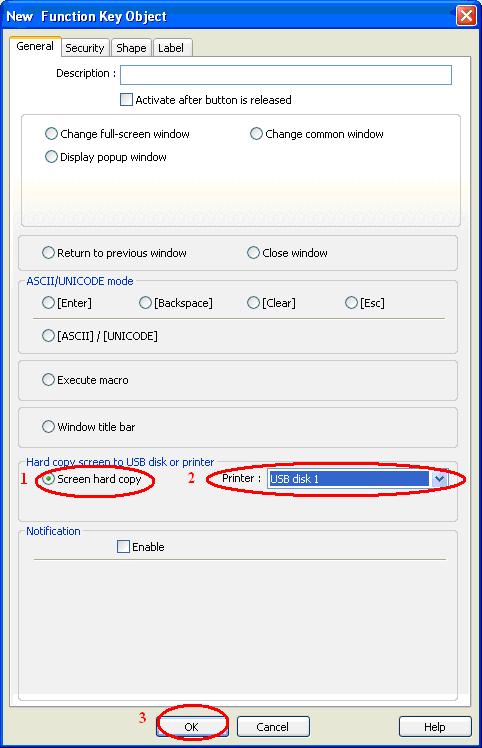
2. In the popup window, check the “Screen hard copy” radio box under the “General” tab. Set the printer to “USB disk 1”. Click “OK” to finish
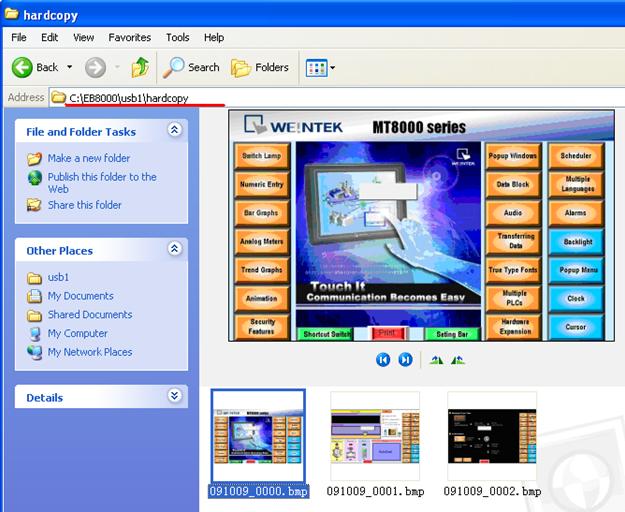
3. Start off-line simulation. Click the print button that is created in the previous step to capture the simulation screen and save it as an image file under the path “\usb1\hardcopy”.
The image is saved in the following path C:\EasyBuilder Pro\usb1\hardcopy:
|
|
|
|
Decompile the xob file which uploading in the USB Stick
|
|
|
|
1. Upload the program file from HMI to the USB disk, and then copy it to the PC (or use the file in USB disk directly).
2. Check out the file that was previously copied from the HMI in the file browser. The original file doesn’t have extension file name.
3. Add the extension file name “.xob”.
4. Run EasyBuilder Pro, select “Tool / Decompile”. The “Decompile” dialog box pops up.
5. Click “Browse” button, and find the .xob file that has been added extension name in the previous step.
6. When the .xob file is selected, make sure that the decompile password must be the same as the upload password. Click “Decompile” button to start to decompile. When the “succeeded” message appears, the de-compilation is completed. Click “Exit” to leave.
7. After de-compilation, open the file that was being decompiled (which now becomes *.mtp file). You can edit it using EasyBuilder Pro now.
8. Open the .mtp file, the edit environment is shown below:
|
|
|
|
Translate MT500 Project to MT8000
|
|
|
|
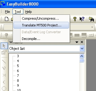
1. Run EasyBuilder Pro, select “Tool / Translate MT500 Project”
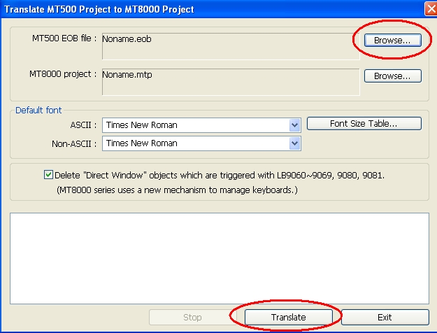
2. Browse the “MT500 EOB file”, select the *.eob file and click “Translate”.
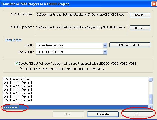
3. When the “succeeded” message is displayed in the dialog box, click “Exit”.
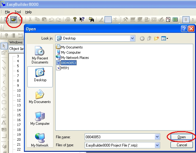
4. In open file dialog, select the *.mtp file and click “Open”.
5. The selected project file is a MT8000 project which can be edit by the user.
Notice: Before translation, please check that if EasyBuilder Pro does support the corresponding PLC type.
(Check out “Edit / System Parameters / Device / New / PLC type“)
|
|
|
|
How to backup a project
|
|
|
An EasyBuilder Pro project contains the source project file (*.mtp), and a number of library files (*.flb, *.blb, *.plb, *.slb, *.snd, *.lbl, and *.glb). These can be individually copied to another location for archiving, or to select theCompress/Uncompress option from EasyBuilder Pro's Tools menu.
Step 1.
Click Compress/Uncompress from Tools menu.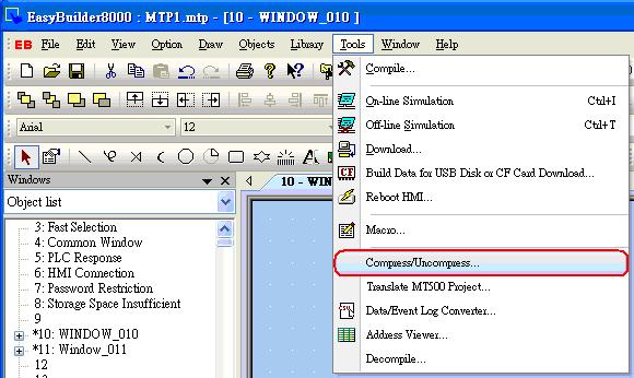
Step 2.
The following dialog is displayed. Click “Browse” to select source project for archiving.
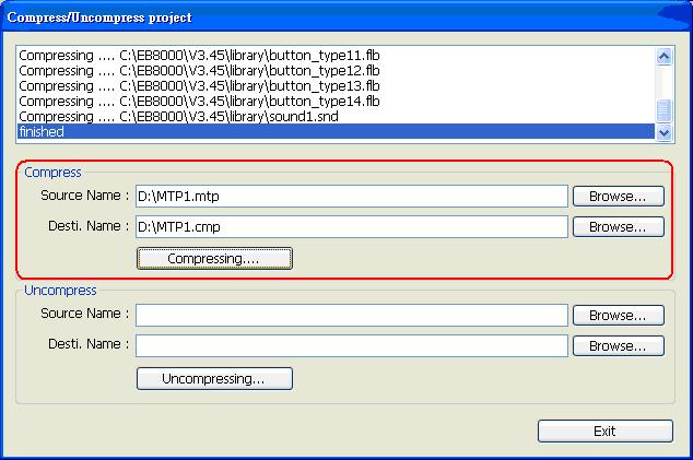
All of the files associated with the project are compressed into a file, with a name of the form *.cmp. The compressed CMP file can be properly archived when this step is successfully completed. |
|
|
|
Switch MT8000 Project between HMI Models
|
|
|
※(Take the switch between MT8056T (320*234) and MT8104X (640*480) for example)
|
|
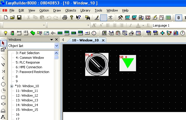
1. The following picture is the MT8056(320*234) project before switching the HMI model.
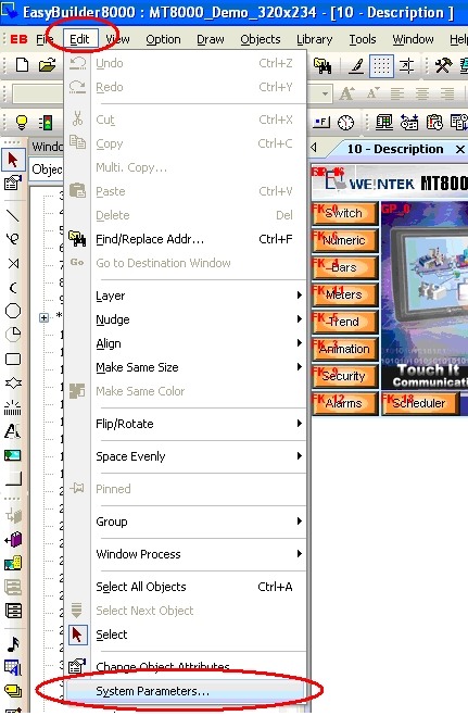
2. Click ”Edit”, select “System Parameters”.
3. Switch to the “Model” tab, select MT8104X (640*480) from the “HMI model” pull-down list.
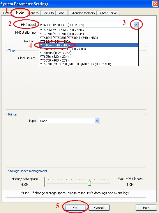
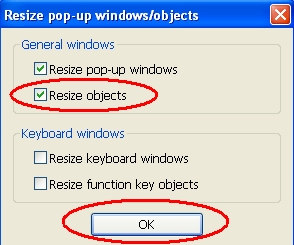
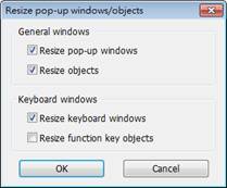
4. Click “OK” button. When the “Resize pop-up windows/object” dialog appears, check the options that you require. For example, If you want to resize objects, just check the “Resize objects” check box in the “General windows” group. The objects of the project will be resized in scale.
5. Click “OK” button to complete the switching process between HMI models. The following picture shows the MT8104X (640*480) project after switch.
|
|
|
|
Download Start Up Screen
|
|
|
MT8000/6000 i series HMI supports users to define their own startup screen, such as enterprise trademark logo, etc. The format of the picture used is BMP and can not exceed the resolution.
The assigned BMP picture will be downloaded to HMI. After downloading, HMI will reboot, this picture will be shown after rebooting, and then load in the project. Users are allowed to use their logos as the start up screen through this method.
Note: Only support i series and OS Image 20090415 or later)

There are 2 ways to download start up screen as shown below:
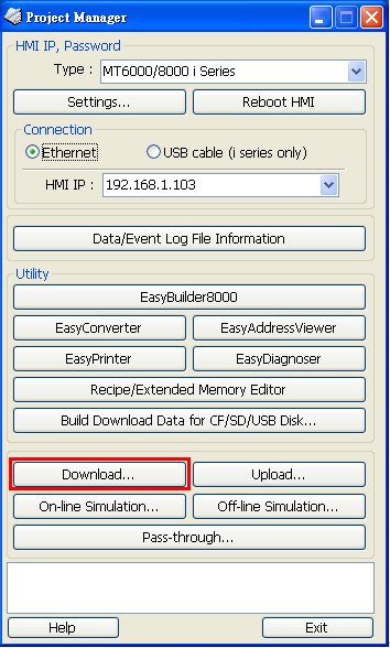
1. Project Manager
1-1 Open Project Manager
1-2 Click [Download]
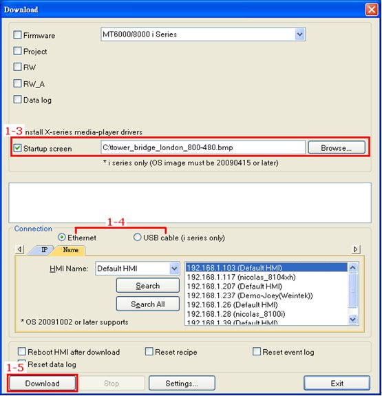
1-3 Select a BMP picture that suits the size of HMI screen,
Ex: MT8070iH uses a 800*480 picture.
1-4 Set the IP address or use a USB cable.
1-5 Click [Download]; reboot HMI to see the successfully set picture display when HMI starts up.
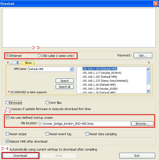
2. EasyBuilder Pro
2-1 Click [Tool] then select [Download]
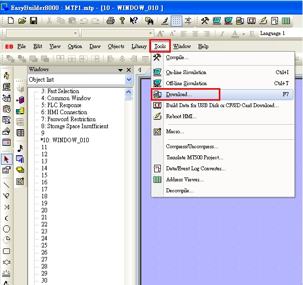
2-2 Select a BMP picture that suits the size of HMI screen,
Ex: MT8070iH uses a 800*480 picture.
2-3 Set the IP address or use a USB cable
2-4 Click [Download]; reboot HMI to see the successfully set picture display when HMI starts up.
|
|
|
|
EasyBuilder Pro - Alignment
|
|
|
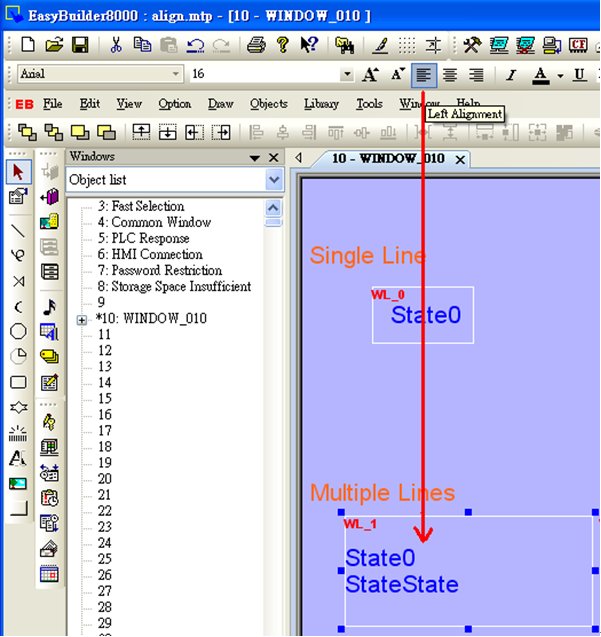
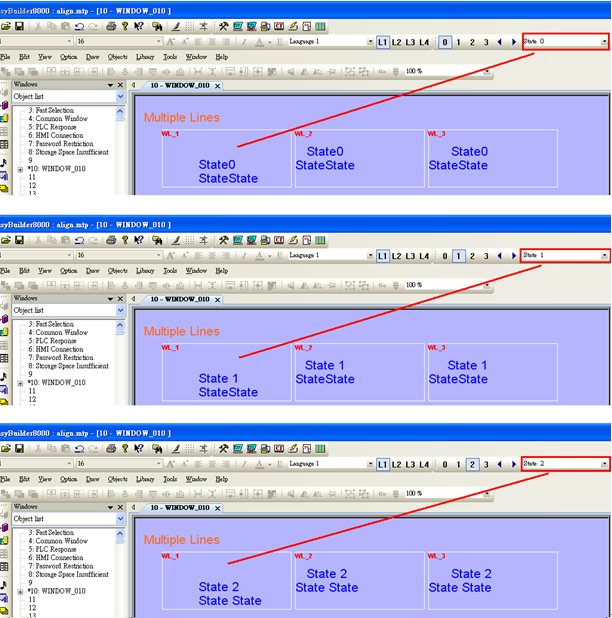
In EasyBuilder Pro, there are two different ways to align the text on the object, one is to click the icons on the toolbar and the other is to set on object setting dialog.
- By clicking the icons on toolbar (Left Alignment | Center Alignment | Right Alignment), the text, no matter single-lined or multi-lined, will be seen as one single label and will align to the outline of the object.
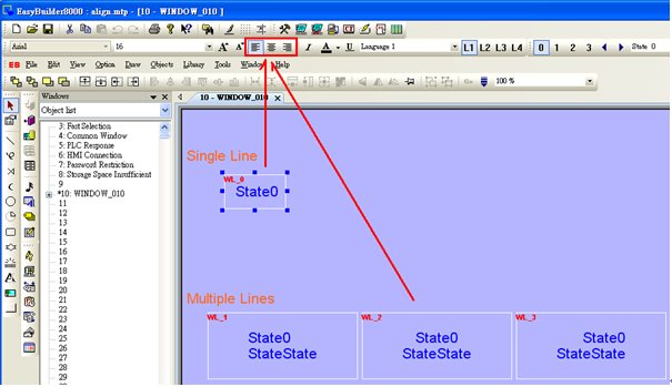
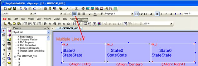
- By setting Label>>Align on object setting dialog, the multiple lines of the text will align in the way set. This is a line by line alignment.
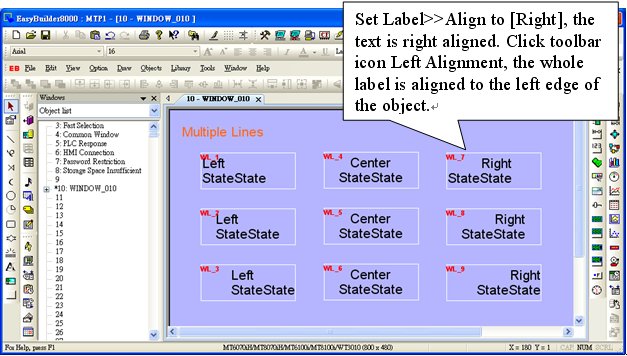
- The line by line alignment of the multi-lined text can be done using Label>>Attribute selection on object setting dialog.
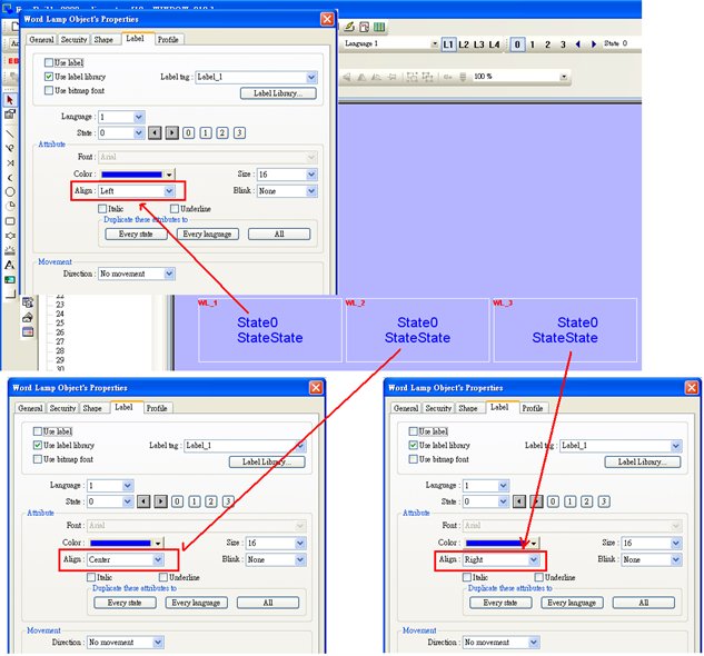
- If an object is set to [Left] for [Align], when clicking [Left Alignment] on toolbar, the multi-lined text will be aligned along the left edge of the object.
- If object text is set with multiple states, tick [Tracking], in this way when moving text in one state, the texts of other states will also be moved in the same way.
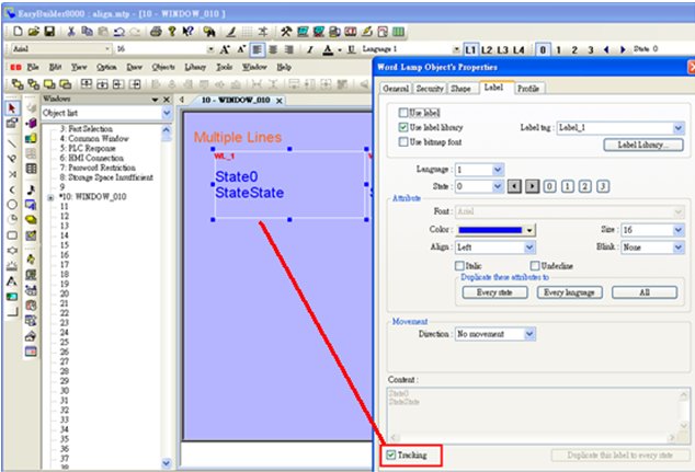
- Move object text in state 0; check the other states to see if the texts in those states all move the same way as in state 0. If [Tracking] is not selected, only text in one state will be moved.
|
|
|
How to download project by Ethernet
|
|
|
This FAQ explains how to download project file to HMI via Ethernet.
Applicable models: eMT Series, iE Series, XE Series, mTV Series, i Series
Non-applicable models: cMT Series
HMI Settings
Step 1. Click on the  Arrow icon in the lower-right corner of the screen. Arrow icon in the lower-right corner of the screen.
Step 2. The following four icons will be shown, click the first Gear icon.

Step 3. Enter password (default is 111111). If the password is correct, the System Settings window opens.
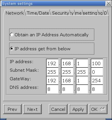
Step 4. In Network tab, set the IP address. Select [Obtain IP Address Automatically] to get IP settings automatically, or select [IP address get from below] to specify an IP address. After setting click [Apply] or [OK] to finish.
Step 5. In Security tab, set the project upload/download password. Click [Download Password] and enter the password. By default, the download password is 111111.
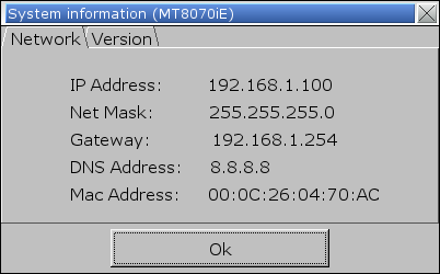
Step 6. When finish setting and leave System Settings window, click the Arrow icon again. Select the Notepad icon to find the IP address of the HMI.

PC Settings
Step 1. Click the Start button and then click [Control Panel]. Under [Network and Sharing Center] click [View network status and tasks]. Click [Local Area Connection] » [Properties], and then double click [Internet Protocol Version 4 (TCP/IPv4)] to open the settings page.
Step 2. Set the network on PC to the same settings as HMI. For example, as shown in the preceding figure, the HMI IP is 192.168.1.100, so the IP of the PC should be 192.168.1.xxx, where x stands for any number.
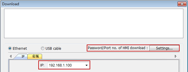
Step 3. To download the project, set the IP and download password in Download window.
Download PDF
|
|
|
MT8000/6000 Touch Panel Adjust and System Initialization
|
|
|
|
1. Switch SW1 to ON position (as shown in picture 1). Press “Reset” or re-plug in the HMI.

<< picture 1 >>
2. Touch panel calibration screen is shown as follows. Put the HMI screen perpendicularly to your line-of-sight, and point your finger at the center of the cross icon displayed on the screen. The cross icon will appear in five positions of the screen: upper-left corner, upper-right corner, lower-right corner, lower-left corner and the center, as shown in (picture 2).

<< picture 2 >>
3. The HMI will automatically restart after finishing calibration. Afterwards, a warning message will appear (as shown in picture 3).

<< picture 3 >>
4. The warning message shows “Restore to default password?”. Users can select “Yes” to restore password or select “No” to discard. If there is no response from the user within 10 seconds, the warning message will automatically be closed.
Notice: If no further operation other than calibration process to make, click “No”.
5. Click “Yes” button. A popup window would show up (as shown in picture 4).

<< picture 4 >>
6. The popup window will check out again if the user really wants to restore the password and will ask the user to enter “yes” and click “OK” button to confirm it. If the user doesn’t want to restore password, click “Cancel”.
7. The password of factory default setting is 111111 for MT8000/6000 series. After initialization process, the project files and data stored in the touch panel HMI will be completely erased.
8. The upload and download password need to be reset in order to transfer project files correctly after initialization (as shown in picture 5).

<< picture 5 >>
|
|
|
|
Notes on USB Cable
|
|
|
The following are some important points relevant to USB cable:
HI-SPEED USB Revision 2.0 SHIELDED 24AWG
1. The PC must support USB 2.0 or USB 3.0.
2. Use a double shielding USB cable: Foil+ Braid Shield.

3. The length of the cable should be limited to less than 1.8 meters.
4. If a desktop is used, the USB cable must be plugged into the back panel instead of the front. If a laptop is used, please remove the external power supply.
5. When downloading a project through USB cable, please remove all the other devices that are connected to HMI.
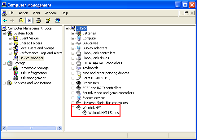
6. If download fails, the possible cause can be the incompatible USB driver on PC. Go to Computer Management » Device Manager to check if the correct USB driver is installed. If not, please go to the installation folder of EasyBuilder and find the usbdriver folder, to manually update the driver.
|
|
|
How to use VNC server
|
|
|
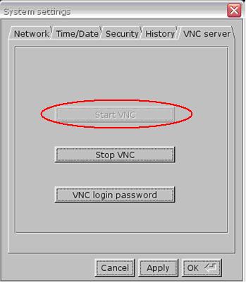
1. Enable VNC server and set login password on HMI System Settings / VNC server tab.
2. Install Java for Internet Explorer or install VNC viewer.
Java web site: http://java.com
VNC viewer: ftp://ftp.weintek.com/MT8000/utility/vnc-4_1_2-x86_win32_viewer.zip
VNC viewer for Pocket PC:
ftp://ftp.weintek.com/MT8000/utility/zoomVNC.CAB
http://zoomvnc.com/
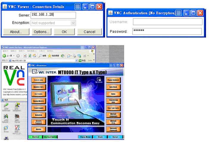
3. Execute IE, and enter IP address of HMI: http://192.168.1.28 (example)
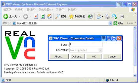
Or execute VNC viewer, and enter HMI IP address and password.
Note:
(1) Only available for one user to login to VNC at the same time.
(2) HMI will reject VNC connection if no operation done for one hour.
|
|
|
TCP Port List
|
|
|
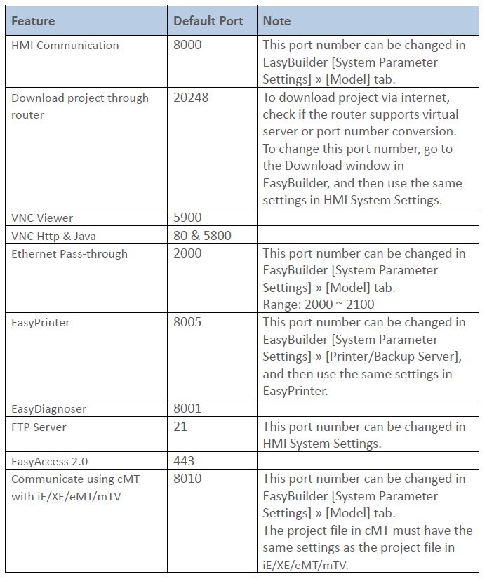
This FAQ introduces the TCP ports used for certain HMI features.
Download PDF
|
|
|
How to use the fonts not supported in EasyBuilder?
|
|
|
Certain fonts can be used in Microsoft Office but cannot be used in EasyBuilder. The possible reason is that these fonts have different names in Control Panel on PC and in Windows Registry. Therefore in EasyBuilder these fonts cannot be selected and used. This document explains the solution to use these font files in EasyBuilder.
Supported software version:
EB8000 V465.05 and later versions
EBPro V300.03 and later versions
A.
Step 1. Use Microsoft Office Word to check if the font can be displayed correctly. If not, copy the font file to Control Panel\Fonts and restart EasyBuilder to check again.
Step 2. If the font is still not displayed in EasyBuilder, check if it works in Word. If it displays correctly in Word, copy the font file from Control Panel\Fonts to EasyBuilder\Windows_font folder and restart EasyBuilder to check again.
When finished, if the font still cannot be displayed in EasyBuilder, the reason would be the difference in font names. For example, the font name in Word is in double-byte characters (As in Traditional Chinese, Simplified Chinese, Korean, Japanese etc.) where in Windows Registry it uses an English name, or, it uses English name in Word where a double-byte character name is used in Windows Registry. The following steps explain the solution.
Example 1
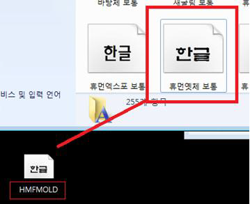
The Korean font “휴먼옛체” uses a Korean font name in Word but an English font name in Windows Registry.
Step 1. Copy “휴먼옛체” font file from Control Panel\Fonts to the desktop to see the font name.
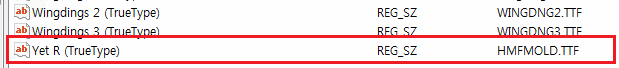
Step 2. Run Microsoft Registry Editor (Regedit). Under the directory: \HKEY_LOCAL_MACHINE\SOFTWARE\Microsoft\Windows NT\CurrentVersion\Fonts, find the corresponding name of the font. As shown in the following figure, the corresponding font name of “휴먼옛체” is Yet R.
Step 3. Open the FontTableName.xls file under EasyBuilder installation directory and enter the English font name in column A, and the Korean font name in column D.

Step 4. Restart EasyBuilder to select the font.
Example 2
The Chinese font “方正大标宋繁体” uses an English font name in Word but a Chinese font name in Windows Registry.
Step 1. Copy “方正大标宋繁体” font file from Control Panel\Fonts to the desktop to see the file name.
Step 2. Run Microsoft Registry Editor (Regedit). Under the directory: \HKEY_LOCAL_MACHINE\SOFTWARE\Microsoft\Windows NT\CurrentVersion\Fonts, find the corresponding name of the font.

Step 3. Open the FontTableName.xls file under EasyBuilder installation directory, enter the English font name in column A, and the Chinese font name in column B. (If the Simplified Chinese OS is used, enter the Chinese font name in column C.)

Step 4. Restart EasyBuilder to select the font.
Note:
n The columns in FontTableName.xls correspond to specific languages and therefore cannot be modified or deleted.
n When using Simplified Chinese font file in Traditional Chinese OS, the Chinese font name entered in FontTableName.xls should be in column B, not column C.
|
|
|
How to do floating point calculations with integers?
|
|
|
To gain a result with decimal place when dividing integers, please convert the integer to float first.
Please see the following Macro. D8=5 is the integer value gained from PLC.
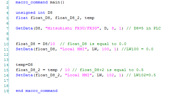
Line 10: Since D8 is an integer, D8/10 is performed as an integer operation and the result is 0. The result is then written to a float variable, float_D8, therefore float_D8 is 0.0.
Line 15: Since temp is a float, temp/10 is performed as a float operation and the result is 0.5.
Download PDF
|
|
|
How to correctly display the project content in different DPI settings?
|
|
|
The computer display resolution is getting higher and higher, in order to display the text clearer, changing the DPI is a choice. However, this also influences the EasyBuilder project display. Incorrect display can happen due to the difference in DPI settings from one computer to another. To avoid this, please follow the steps to adjust the DPI setting.
Checking the current size of text
Step 1. Click the right mouse button on the desktop and select [screen resolution] » [Resolution]。
Adjusting the DPI of EasyBuilder project
Step 1. Launch EasyBuilder Pro, select [Tools] » [Text DPI Setting].
Step 2. Choose [Select the previous PC’s text DPI setting], adjust the DPI to the same setting as the previous computer used to create this project. The text will be correctly displayed. Click [OK]; the system will generate a BAK file for future reference.
Step 3. The DPI setting will be stored in the system. Next time when opening this project file, the previous PC’s DPI setting will be used.
Download PDF
|
|
|
How to Connect Multiple Devices via One Serial Port?
|
|
|
To connect multiple devices via a single serial port, certain station number can be specified when configuring the serial port in System Parameter Settings » Device List. This FAQ explains the syntax of the variables that can be used when setting the station number for the read/write address of an object.
When setting the read/write address of an object, use the syntax “SN#address”. As shown in the following figure, 2#1 indicates station number 2, address 3x1.
Or, use syntax “VARn#address”. The valid VARn range is from LW-10000 (VAR0) to LW-10015 (VAR15). As shown in the following figure, VAR5#2 indicates that the station number is determined by the value in LW-10005 (VAR5).
|
|
|
How to Backup Data to Server and Update in Excel?
|
|
|
To update data backup in remote backup server to an Excel file, please follow the steps below.
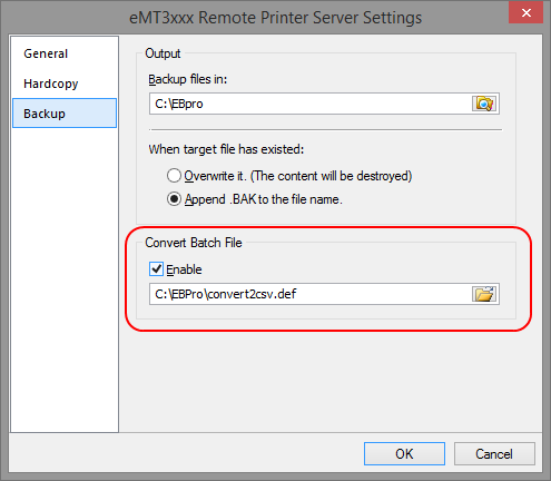
For details of Backup object settings in EasyPrinter and EasyBuilder, see Chapter 26 EasyPrinter and Chapter 13.24 Backup.
Step 1. In EasyPrinter, under Convert Batch File select [Enable] check box. This enables converting file backup into Excel file.
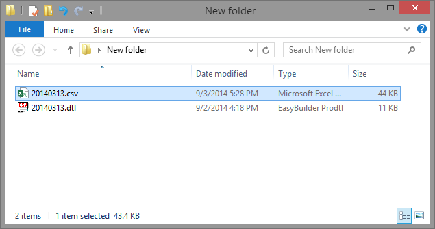
Step 2. When backup file to server, a .csv file is generated.
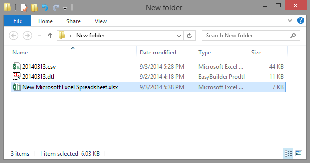
Step 3. Create a new Excel file.
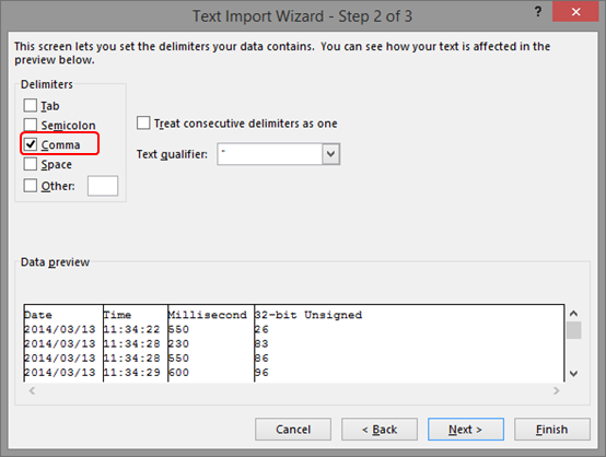
Step 4. Open the created Excel file, import the content in the .csv file by clicking [Data] \ [Get External Data] \ [From Text].
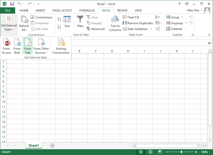
Step 5. During import, select [Comma] to be the delimiters.
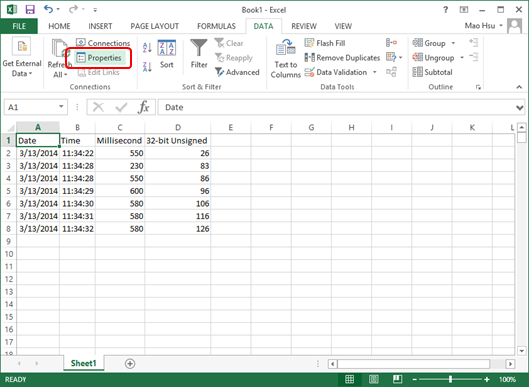
Step 6. When finished, the content in the .csv file can be viewed in Excel. Click [Data] and set [Properties].
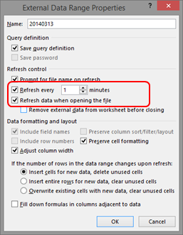
Step 7. Set the time interval to refresh the Excel file, and select [Refresh data when opening the file].
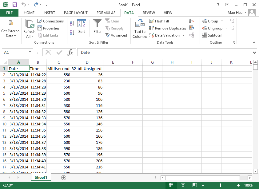
Step 8. In this way, when backup file to server, the generated .csv file is automatically imported to Excel, therefore users can always view the updated data when opening the Excel file.
Download PDF
|
|
|
How to set HMI IP on HMI?
|
|
|
This FAQ explains how to view or set HMI IP address on HMI by using System Setting Toolbar.
Applicable Models: eMT, iE, XE, mTV, i Series
Non-applicable Models: cMT Series
Step 1. Hit the leftward arrow icon  in the lower-right corner of HMI screen. in the lower-right corner of HMI screen.
Step 2. The following four icons open, hit the gear wheel icon.

Step 3. Enter password (Default: 111111) to open System Settings dialog box.

Step 4. In Network tab, two options exist:
[Obtain an IP Address Automatically]: Get IP automatically.
[IP address get from below]: Set IP manually.
Select one of the options and click [Apply] and then click [OK] to save the settings.
Step 5. Leave System Settings dialog box, hit the leftward arrow icon again, and then hit the notepad icon to view Network information.


Download PDF
|
|
|
How to display project in portrait mode on HMI
|
|
|
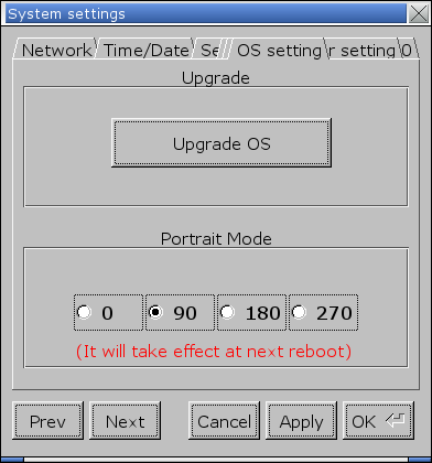
If the project file is edited in portrait mode, the following settings help to display project correctly on HMI.
Step 1. On HMI, open [System settings] » [OS setting], and select [90] or [270] in Portrait Mode group box.
Applicable models: eMT, iE, XE, mTV, i Series
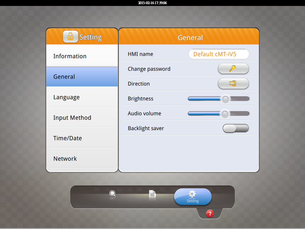
For cMT-iV5 model, open [Setting] » [General] » [Direction] to set portrait mode.
Step 2. Launch EasyBuilder, click [File] » [New] and select [Portrait] as display mode.
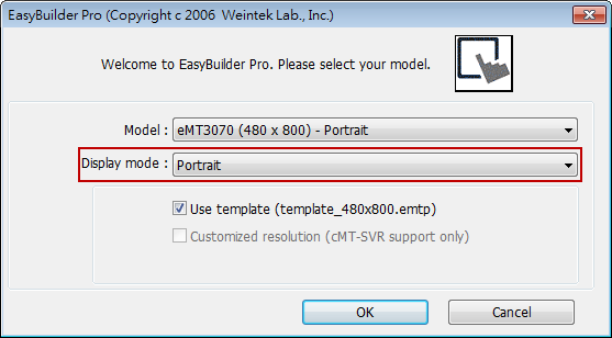
Please note that setting project in Portrait mode before editing the project is necessary. During project editing, the display mode cannot be changed.
Download PDF
|
|
|
Why can’t I open cMT Viewer or the screen is blank after opening cMT Viewer?
|
|
|
When using an older computer to open cMT Viewer, sometimes the system may show error message or the screen may be blank. This document shows how to solve this issue.
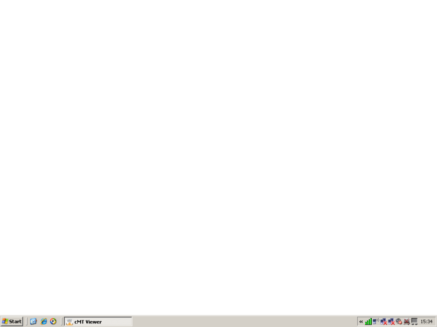
The cMT Viewer application requires a 3D graphic API, OpenGL (Open Graphics Library) newer than version 2.1. If you use an older PC or laptop that runs the OS like Windows XP or Windows Vista, the driver of the graphic chips may be outdated, and doesn’t support newer version’s OpenGL. Please download the latest driver of the graphic chip from the supplier.
Download PDF
|
|
|
How to change the model of the project?
|
|
|
The following example shows how to change a MT8070iE (800 x 480) project to an eMT3120 (1024 x 768) project.
Step 1. Open the MT8070iE project.
Step 2. Click [Edit] button » select [System Parameters] » [Model] tab » select [eMT3120/eMT3150 (1024 x 768)].

Step 3. After click [OK], the “Resize pop-up windows/objects” dialog box will be displayed, please selected the needed settings. For example, if [Resize objects] check box is selected, the objects will be resized according to the screen size of the new model.
Step 4. Click [OK] to complete the process. Now you will see the eMT3120 (1024 x 768) project.
Download PDF
|
|
|
Notes on HP Printer
|
|
|
Weintek HMI (i, iE, XE, eMT, mTV Series) support HP Printer PCL 5 protocol and PostScript 3 printer control language.
Here are some notes on choosing HP printer:
1. Choose a printer that supports PCL5 or later versions. This type of printers should support PCL 5 protocol because PCL language is backward compatible.
2. Choose a printer that does not require additional driver plug-in.
On HPLIP website: (http://hplipopensource.com) you can find the detailed information about HP printers. Find “Other Information” and see the Description column. If it shows “None”, the printer might work with HMI. If it shows information other than “none”, the printer will not work with HMI.
|
Item
|
Description
|
Notes
|
|
Driver plug-in
|
None
|
See note.
|
3. When using an HMI with Ethernet, please use EasyPrinter to send the image to PC for printing. EasyPrinter working as a printer server, HMI’s print jobs can be sent to EasyPrinter via Ethernet and be printed by a printer supported by the PC.
Download PDF
|
|
|
Port Number 8000 Occupied
|
|
|
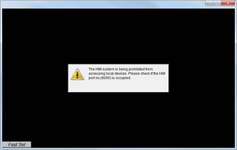
When running project simulation on PC, if the following message is displayed, the possible reason is that the communication port number 8000 is occupied by other application, and therefore the simulation cannot be carried out. This FAQ explains how to check and change port number to solve this problem.
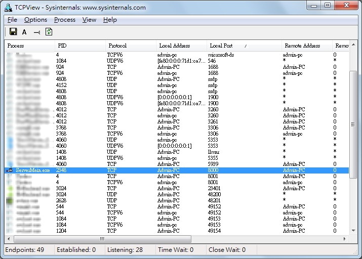
Step 1. Please use TCPView to check if port no. 8000 is occupied. You can download TCPView using the following link:
https://technet.microsoft.com/en-us/sysinternals/tcpview.aspx
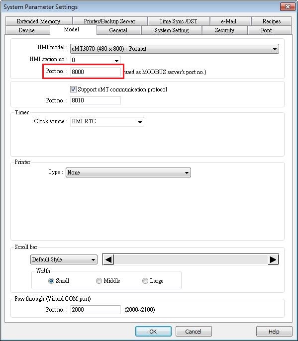
Step 2. If port no. 8000 is occupied, you can change the port number in EasyBuilder System Parameter Settings » Model tab.
Download PDF
|
|
|
How to download project and history data using USB disk or SD card
|
|
|
Utility Manager can build download data and save the data in USB disk or SD card. The data such as project file, recipe data, and history data can be downloaded to HMI using the USB disk or SD card, as a way to update HMI data.
Please note that the described methods are not applicable for cMT Series.
In this document, “USB/SD” refers to USB drive or SD card.
[Build Download Data for SD/USB Disk]
In Utility Manager click [Publish] » [Build Download Data for SD/USB Disk] to create downloadable data including project file, recipe data, or history data…etc. into USB/SD.
Step 1. Launch Utility Manager and click [Publish] » [Build Download Data for SD/USB Disk].
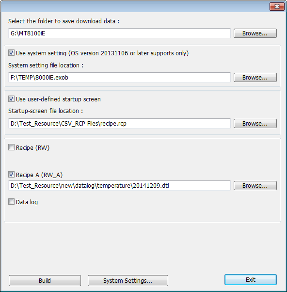
Step 2. Specify the directory of the USB disk or SD card, and the directory of data files, and then click [Build]. For ease of file management, it is recommended that a dedicated folder be created in the USB/SD. You can use a folder name that’s easy to identify, for example, the HMI name or model name.
As shown in the following figure, the folder to save download data is:
G:\MT8100iE
Step 3. If the data is successfully built, a notification message ‘creating successful!’ will show.
[Download to HMI]
Step 4. Insert USB disk or SD card into HMI, the following window will be displayed.
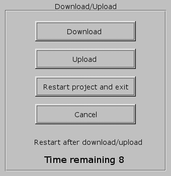
Step 5. Hit [Download], enter HMI download password, select [Download project files] or [Download history files], and then hit [OK]
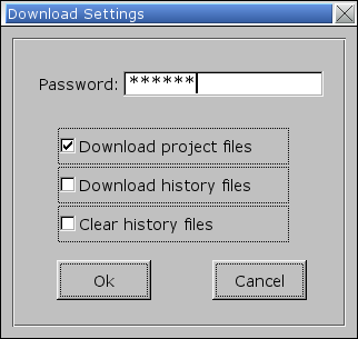
Note: History file includes recipe data (RW, RW_A), and data sampling.
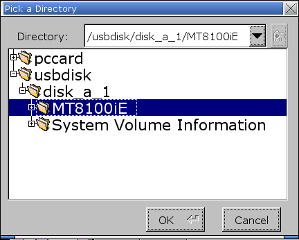
Step 6. Select the directory that has the download file and then hit [OK]. Choose the same directory whether downloading only the project file, only the history data, or both. As shown in the following figure, select the MT8100iE folder created in step 2.
Step 7. During download, the message: “Download Project Files…” or “Download History Files…” is displayed.

Step 8. After download, HMI program will start again.
Download PDF
|